Wire the electronics
Why each component on the BOM was chosen, and what to know when re-sourcing or substituting it. The BOM is the procurement reference; this doc is the why behind it.
Wiring diagram
Section titled “Wiring diagram”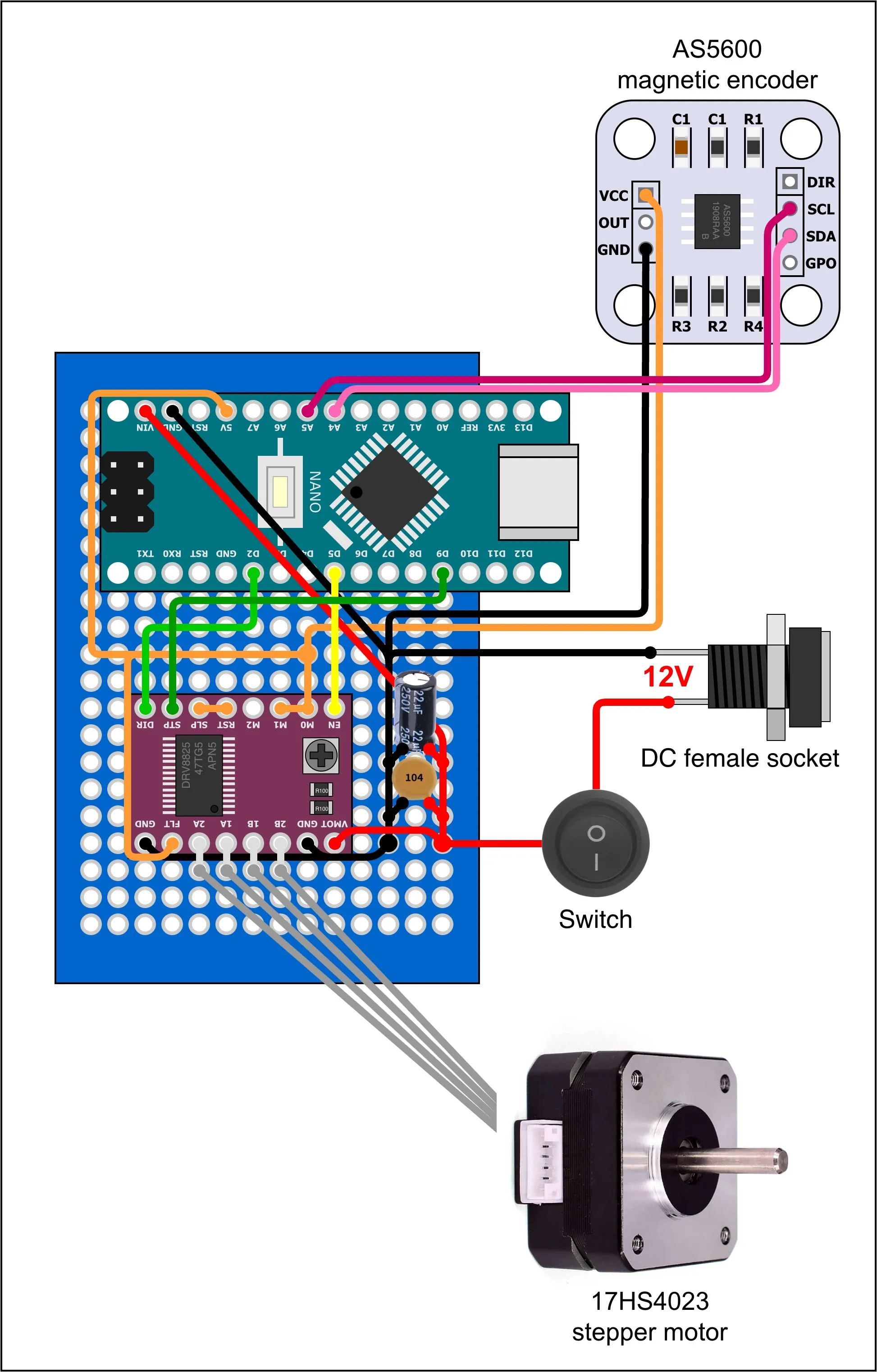
All components live on a single 40 × 60 mm protoboard. The diagram
above is the canonical layout; its editable drawio source and the
component-level photos are in
hardware/.
Microcontroller — Arduino Nano (ATmega328P, 16 MHz)
Section titled “Microcontroller — Arduino Nano (ATmega328P, 16 MHz)”- 32 KB flash / 2 KB SRAM is enough for the LowLevelServer binary protocol plus AS5600 I/O plus AccelStepper at 1 kHz internal step rate. The distilled policy fits too, with margin — 689 parameters in 2.7 KB of flash.
- During training, the heavy lifting (sysid fitting, SAC, distillation) runs on the host PC and the Nano just shuttles state and commands at 2 Mbaud. Once the policy is distilled and flashed, the host is gone.
- USB-C variant preferred over Mini/Micro for connector durability — the rig gets re-plugged frequently during firmware iteration.
- Any CH340-based clone works; driver is built into modern macOS / Linux.
Stepper motor — NEMA17 17HS4023 (1 A rated, 22 mm body)
Section titled “Stepper motor — NEMA17 17HS4023 (1 A rated, 22 mm body)”- Under-loaded by design. The arm + pendulum is <50 g and the only rotational inertia the motor fights is the arm itself (~1.5 × 10⁻⁵ kg·m²). Phase current rarely exceeds ~0.3 A. The 1 A rating is ~3× headroom against ever stalling.
- Short-body 17HS4023 over the longer 17HS4401. The motor is bolted vertically, so its mass is below the rotation axis and doesn’t load the bearings — but the shorter body still trims rig height and cost. With the loads this rig sees, the longer motor’s extra torque is wasted.
- Substituting a heavier or stronger motor would add mass and cost without benefit; substituting a smaller one (e.g. NEMA14) risks losing steps under sudden swing-up commands.
Stepper driver — TMC2209 (recommended)
Section titled “Stepper driver — TMC2209 (recommended)”The TMC2209 is the recommended driver for this rig. Its StealthChop2 chopper plus internal 256-microstep interpolation makes the motor effectively silent, and it removes torque ripple that the balancing policy previously had to fight. Measured on the standalone RL controller with an unchanged policy, swapping DRV8825 → TMC2209 improved every metric at once (5-minute captures at 50 Hz):
| metric | DRV8825 | TMC2209 |
|---|---|---|
| balanced fraction | 0.996 | 1.000 |
| longest unbroken hold | 165 s | 299 s (whole run) |
| drops | 3 | 0 |
| pendulum angle σ | 3.01° | 2.53° |
| arm angle σ | 10.5° | 7.1° |
| mean |action| | 0.413 | 0.325 |
Quieter and calmer: the halved arm motion is the same quantity that extensive reward-shaping experiments failed to improve in software.
Read that as the driver’s contribution with the policy held fixed. Both columns are beaten by policies fine-tuned on the rig itself, so the interesting question is what the driver costs once each side is trained properly.
That comparison has since been run on one rig, swapping only the driver and retraining from the same simulation teacher:
| after fine-tuning | DRV8825, 90 ep | TMC2209, 30 ep | TMC2209, 60 ep |
|---|---|---|---|
| balanced fraction | 1.000 | 0.993 | 1.000 |
| mean |action| | 0.275 | 0.236 | 0.177 |
| pendulum angle σ | 1.83° | 1.62° | 1.23° |
| arm angle σ | 9.4° | 11.1° | 6.3° |
| arm speed RMS | 0.86 | 0.76 | 0.58 |
The TMC2209 matched 90 episodes of DRV8825 tuning in 30 — about six minutes of rig time against eighteen — and kept improving from there. Whether the DRV8825 would eventually catch up given more episodes was not tested; what is measured is that it is behind at every budget tried.
Why it runs smoother
Section titled “Why it runs smoother”Watch the tip of the arm at low speed and you can see the difference: a DRV8825 moves it in small jumps, a TMC2209 glides. Two reasons.
The TMC2209 smooths the gaps between your microsteps. MS1/MS2 still set what one STEP pulse is worth — that is your command resolution, and it must match the sketches. But between those commanded positions the TMC2209 fills in up to 256 microsteps of its own (interpolation), so the coil currents move ~8× more finely than the 1/32 you ask for. The DRV8825 goes straight to each commanded microstep and does nothing in between.
The two chips control coil current differently. The TMC2209 sets coil voltage and lets the current follow (StealthChop), which tracks the ideal sine wave closely at low speed. The DRV8825 switches current on and off against a threshold (chopping), which is least accurate at low current — exactly where the in-between microsteps live. When the current misses its target the rotor is not where the step counter thinks, and the intermediate microsteps collapse toward the nearest full step. That collapse is the jumping you see.
One limit applies to both: a single 1/32 microstep asks for only ~5 % of the motor’s holding torque, roughly the same as the motor’s own cogging (detent) torque. So the rotor tends to sit still until a few microsteps of command have built up, then snap to catch up. Finer microstepping only helps if the driver’s current accuracy is good enough to be worth believing.
For the RL controller this costs twice: the policy’s motor_pos comes from the
step counter, so mid-snap it is told a position the arm has not reached yet, and
each snap is a small kick into the pendulum. Neither is modelled in sim, which
is why the DRV8825 rig needed 90 fine-tuning episodes to reach the calmness the
TMC2209 rig reached in 30. Learnable — but it costs rig time.
Wiring — not a like-for-like pin swap
Section titled “Wiring — not a like-for-like pin swap”Both carriers are 8 pins per side and line up positionally, but the middle functions differ:
| position | DRV8825 | TMC2209 |
|---|---|---|
| 1 | EN | EN — also active-low, so firmware is unchanged |
| 2–3 | M0, M1 | MS1, MS2 — different microstep encoding |
| 4 | M2 | UART_TX |
| 5 | RESET | UART_RX (PDN_UART) |
| 6 | SLEEP | CLK |
| 7–8 | STEP, DIR | STEP, DIR |
- Remove the RESET–SLEEP solder bridge. The DRV8825 needs it; on a TMC2209 those positions are UART_RX and CLK, so the bridge becomes an invalid CLK↔PDN_UART link (PDN_UART’s internal pull-up then holds CLK statically high). Symptom: the motor never fully releases when disabled — notchy, skipping back-drive, which wears the printed D-shaft slot over time. Fix: remove the bridge and add nothing. CLK floating selects the internal 12 MHz oscillator; PDN_UART floating enables standstill current reduction.
- Coil pin order differs (DRV8825
B2 B1 A1 A2vs TMC22092A 1A 1B 2B). Identify each coil with a multimeter — the wire pair with low resistance between them is one coil — then wire one coil to 1A/1B and the other to 2A/2B. On this rig’s harness a 180° connector flip happens to produce a valid mapping. - Microstepping: the mode pins sit at the same board positions but decode differently. See Microstepping below for both tables and the recommended setting.
Vref / current tuning — the TMC2209 sets RMS, not peak
Section titled “Vref / current tuning — the TMC2209 sets RMS, not peak”This is the one that bites. A DRV8825’s Vref sets a peak current; a TMC2209’s sets RMS. Carrying over a DRV8825-style number therefore over-drives the motor: a factory-default pot at 1.2–1.3 V is ≈0.9 A RMS (≈1.3 A peak) into a 1 A motor, which gets the motor burning hot within five minutes — enough to risk demagnetising the rotor and softening the printed motor mount.
Probe the pot wiper / Vref pad against GND with the board powered and the motor idle:
| Vref | ≈ I_RMS | ≈ I_peak | notes |
|---|---|---|---|
| 0.7 V | 0.50 A | 0.70 A | conservative, runs cool |
| 0.9 V | 0.64 A | 0.90 A | recommended — matches the DRV8825 setup’s effective RMS |
| 1.1 V | 0.78 A | 1.10 A | at/above the motor rating; expect heat |
This rig runs 0.908 V: only slightly warm after 7+ minutes of
continuous balancing, with balance unaffected (mean |action| 0.325 leaves
ample torque headroom). Because the exact Vref→current relation depends on
the carrier’s sense resistors, trust the thermometer over the formula —
after a few minutes the motor should be warm enough to notice but
comfortable to keep a hand on. Too hot → lower Vref. Sluggish, or the arm
drifts off-centre / loses its commanded position (lost steps) → raise it.
Wiring UART and calling rms_current() removes the guesswork entirely if
you want an exact figure.
Stepper driver — DRV8825 (original, still supported)
Section titled “Stepper driver — DRV8825 (original, still supported)”The rig was originally built and tuned around the DRV8825, and every sketch still supports it — wire it for 1/32 per Microstepping below and restore the RESET–SLEEP bridge.
- Vref set to 0.45 V → ~0.9 A current limit per phase (90 % of the motor’s 1 A rating; this driver’s Vref is a peak limit). Standard 10 % margin keeps the driver and motor below thermal limits indefinitely.
- 8.2–45 V supply range; 12 V chosen as the lowest sensible voltage — see “Power supply” below.
- A4988 is another drop-in alternative but tops out at lower current and is audibly louder.
- Set Vref before installing the motor. With the driver powered and the motor disconnected, probe Vref against GND while turning the trim pot.
Vref across drivers
Section titled “Vref across drivers”The Vref-trim procedure is the same for all three, but the relation between Vref and the resulting phase current differs:
| Driver | Imax → Vref | Vref @ 0.9 A target |
|---|---|---|
| DRV8825 | Vref = Imax / 2 (Rcs = 0.1 Ω, standard on Pololu and most clones); peak current | 0.45 V (we ran 0.45 V — close enough) |
| A4988 | Vref = Imax × 8 × Rcs. Pololu carriers use Rcs = 0.05 Ω; some clones use 0.1 Ω — check yours | 0.36 V (Pololu) / 0.72 V (Rcs = 0.1 Ω clones) |
| TMC2209 | RMS current, carrier-dependent — see the table above, or the TMC220X Vref calculator | ≈0.9 V (0.64 A RMS ≈ 0.9 A peak) |
Microstepping
Section titled “Microstepping”We recommend 1/32 — 6400 steps/rev — on either driver. Both carriers
reach it, and standardising on one ratio means the flashed policy is
trained against the motor-step quantisation it actually deploys at,
whichever driver your rig has. The RL stack models that quantisation
explicitly (MOTOR_MICROSTEPS in pendulum_env.py), and it is the
finest ratio the pair has in common.
The mode pins occupy the same board positions on both carriers but decode differently, so wire your rig from the table for the driver you have — there is no single set of pin levels that gives 1/32 on both. Unconnected pins read LOW: both carriers pull the mode inputs down internally, so “LOW” means leave the pin unwired.
DRV8825 — positions 2, 3, 4 (M0, M1, M2)
Section titled “DRV8825 — positions 2, 3, 4 (M0, M1, M2)”| M0 | M1 | M2 | resolution | steps/rev |
|---|---|---|---|---|
| LOW | LOW | LOW | full step | 200 |
| HIGH | LOW | LOW | 1/2 | 400 |
| LOW | HIGH | LOW | 1/4 | 800 |
| HIGH | HIGH | LOW | 1/8 | 1600 |
| LOW | LOW | HIGH | 1/16 | 3200 |
| HIGH | HIGH | HIGH | 1/32 | 6400 |
1/32 is also reached by HIGH LOW HIGH and LOW HIGH HIGH, but all
three high is the easiest to build: M0, M1 and M2 are adjacent header
positions, so you can bridge their solder points together on the
protoboard in one pass and take a single wire to logic HIGH. The mixed
combinations need each pin routed individually.
TMC2209 — positions 2, 3 (MS1, MS2)
Section titled “TMC2209 — positions 2, 3 (MS1, MS2)”| MS1 | MS2 | resolution | steps/rev |
|---|---|---|---|
| LOW | LOW | 1/8 | 1600 |
| HIGH | LOW | 1/32 | 6400 |
| LOW | HIGH | 1/64 | 12800 |
| HIGH | HIGH | 1/16 | 3200 |
HIGH LOW is also the least work of the four: MS2 stays unwired on its
internal pull-down, so 1/32 costs exactly one wire from MS1 to logic HIGH.
Position 4 is UART_TX on a TMC2209, not a mode pin — leave it unwired. (A shared socket driving position 4 HIGH would give 1/32 on both drivers, but it puts a driven signal on the TMC2209’s UART line, so we don’t recommend it.)
Then set the sketches to match
Section titled “Then set the sketches to match”MICROSTEPS is a single constant in RLControl.ino,
LowLevelServer.ino and TestMotor.ino; steps/rev, the speed cap and
every rad↔step conversion derive from it. It must also match
MOTOR_MICROSTEPS in pendulum_env.py, which is recorded into each
run’s config.json as motor_microsteps so you can check what a given
policy was trained against.
Smoothness does not depend on this choice on a TMC2209 — it interpolates every input step to 256 microsteps internally regardless. On a DRV8825 the finer ratio does reduce position quantisation, but its microstep current accuracy does not improve much past 1/8, so expect a cleaner observation rather than dramatically quieter running (why).
Power supply — 12 V, 2 A
Section titled “Power supply — 12 V, 2 A”The ideal supply for this rig. Reasoning:
The DRV8825 chops coil current, so supply current ≠ motor phase current. Power balance:
Both phases active plus ~50 mA of logic (Nano + AS5600 + indicators) gives ~0.6 A steady-state, with brief peaks to ~1 A on direction reversals. 2 A is ~3× headroom — the right margin for a cheap wall-wart with no wasted capacity.
3 A and 5 A adapters work fine (verified empirically) but the extra current is unused. What actually matters more than headline amps:
- Regulation quality — a clean 2 A unit beats a noisy 5 A one for ripple. The Nano’s 5 V LDO and the AS5600’s I²C bus get unhappier with messy rails than with low-rated ones.
- Bulk decoupling on the board — the 22 µF on the rail handles the worst of the chopping spikes. If you ever see brown-outs on direction reversals, add a 470 µF near the driver before upsizing the adapter.
- Connector contact — a loose 5.5 mm barrel jack drops volts under spike load regardless of adapter rating.
Why 12 V specifically:
- DRV8825 accepts 8.2–45 V; 12 V is the cheapest sensible choice.
- The Nano’s onboard linear regulator dissipates 12 V → 5 V comfortably. 24 V starts to cook it (the regulator runs hot enough to derate above ~16 V continuous).
- 12 V wall-warts with 5.5 mm barrel plugs are ubiquitous.
Magnetic encoder — AS5600
Section titled “Magnetic encoder — AS5600”- 12-bit absolute angle → 2π / 4096 rad ≈ 0.088° resolution.
Quantisation is modelled in
pendulum_env.py(PENDULUM_LSB_RAD) so the policy sees the same step size sim and real. - Contactless / magnetic → zero friction on the pendulum joint, which is the mechanical DOF we most care about preserving. A contact pot or quadrature wheel would add a friction term we’d have to identify and randomize against.
- I²C at 400 kHz reads in <1 ms — fits comfortably in the control budget.
- The TZT-style AliExpress modules ship with a small diametrically- magnetised disc; no separate magnet sourcing needed.
- Magnet alignment matters. Disc face 0.5–3 mm from chip face,
axially aligned. The AS5600’s
AGC(automatic gain control) register reports magnet strength — check it on first power-up; out-of-range readings indicate a misaligned or wrong-grade magnet. - The DIR pin hardware-defines which rotation counts positive (GND = increasing clockwise viewed from the magnet side, VDD = the reverse) and per the datasheet it should not float. The canonical wiring diagram leaves it unwired, so on these builds the direction is whatever the breakout’s strap resistors set it to. The stack tolerates either (per-rig tare, mirror-symmetric plant), but two rigs built from the same docs can end up as physical mirrors of each other. TODO (issue #4): measure DIR’s strapping on the reference breakout and wire it explicitly to GND.
- 5 V operation (issue #4):
common AS5600 breakouts use a zero-ohm jumper (typically
R1) to select 3.3 V; it reportedly must be removed for 5 V supply. TODO: verify which jumper the reference module uses and document it — these rigs run the AS5600 from the Nano’s 5 V rail.
Decoupling — 100 nF ceramic + 22 µF electrolytic
Section titled “Decoupling — 100 nF ceramic + 22 µF electrolytic”Two-stage decoupling on the 12 V rail at the driver’s VMOT pin:
- 100 nF ceramic (104) handles high-frequency spikes from the driver’s ~30 kHz chopping. The ceramic’s low ESR matters more than its capacity at this point.
- 22 µF electrolytic handles bulk current draw between switching cycles. 22 µF is fine for this rig’s modest loads; if you upsize the motor or see brown-outs on fast reversals, bump to 470 µF before upsizing the supply.
Hookup wire — 26 AWG solid-core
Section titled “Hookup wire — 26 AWG solid-core”- Single gauge across signals + power, because:
- Rig peak current is ~1 A; 26 AWG handles 2.2 A continuously in chassis wiring.
- One stock is easier to manage than separate gauges for signal vs power, and the difference doesn’t matter at these currents.
- Solid-core terminates more reliably in protoboard plated holes than stranded.
- A dedicated thinner gauge for I²C would be overkill at the AS5600 cable’s ~100 mm length.
Power switch + barrel jack
Section titled “Power switch + barrel jack”- An inline SPST rocker on the 12 V rail is far more convenient than yanking the barrel plug. Power-cycling is a frequent diagnostic during firmware development.
- Jack/plug size mismatch (5.5 × 2.1 mm jack vs 5.5 × 2.5 mm adapter plug): the 0.4 mm pin-diameter difference produces a slightly loose fit but reliable contact in practice. If you can find a matched 2.5 mm jack at the same price, prefer it — otherwise the mismatch is harmless.
Things deliberately not on the BOM
Section titled “Things deliberately not on the BOM”- Battery / boost converter. This rig is computer-tethered for the RL pipeline; portability isn’t a goal. The on-device PID firmware could be battery-powered, but cheap LiPo + buck is more diagnostics surface than the use case warrants.
- TVS / protection diodes on the rail. The wall-wart adapters used here are well-behaved; an RC snubber on the motor leads or a TVS at VMOT would be belt-and-braces but isn’t load-bearing for stable operation.
- Logic-level shifters. Nano (5 V) + AS5600 (3.3 V tolerant on I²C with internal pull-ups to 5 V works on this module) — no shifter needed. Other AS5600 boards may differ; check the breakout’s pull-up voltage before assuming.
Related
Section titled “Related”BOM.md— procurement reference (suppliers, prices, qty).3d_printing.md— printing settings and the coin-pause technique for the pendulum link.sysid_runbook.md— measurement protocol that validates the electronics chain works end-to-end.