

IMU calibration and encoder errors
Measured on 2026-10-06 with the IMU in the ATOM. No markers or external cameras.
In short
Section titled “In short”- The zero offsets of the pitch joints are good: δ2 + δ3 + δ4 = 0.2–0.3° (±0.1°). No correction is needed.
- The table tilts 0.54°. The fit finds it with the other parameters.
- J5’s encoder is not linear: it is off by 3.7° peak to peak over ±148°. The Julia package corrects it now: 0.18° peak to peak remains (see J5 correction).
- J2, J3 and J4 have about 1–1.9° of play outside the encoder. The link jumps across the play where the gravity torque on the joint changes sign. J2 also bends.
- These errors do not show in the servo encoders, so they do not show in the circle and ILC results. At 250 mm reach, 1° on J2 is about 4 mm at the flange.
The IMU
Section titled “The IMU”The ATOM’s MPU6886 is on the link between J5 and J6: a J6 turn of ±90° does not
change the gravity reading. At rest the accelerometer measures “up” (1 g).
src/imu_calibration.jl predicts it from the encoder angles:
acc = C · R_SL · R_BL(q + δ)ᵀ · u_B + b| Term | Meaning | Parameters |
|---|---|---|
u_B |
“up” in the base frame (the tilt of the base) | 2 |
R_BL(q + δ) |
URDF forward kinematics of the IMU link, with zero offsets δ | 1 (δ2 + δ3 + δ4) |
R_SL |
how the IMU sits on its link | 3 |
C, b |
accelerometer scale, cross-axis terms and bias | 9 |
Gravity cannot see some parameters:
- J2, J3 and J4 are parallel, so only δ2 + δ3 + δ4 changes the IMU orientation.
- δ1 merges with the heading of the base, and δ5 with the IMU mounting.
- The tilt of the base is a property of the mounting. After the arm moves to another table, a wall or a ceiling, fit the tilt again. The other parameters belong to the robot.
Static poses
Section titled “Static poses”scripts/static_poses.jl moved the arm through 48 random poses inside the
lab workspace, plus the zero pose every 10 poses
and J6 at ±90°. It held each pose for 6 s and read the joint state and the IMU
at about 70 Hz. Recording on the Pi: tools/python/recordings/static/20261006-105425_static_*.csv.
scripts/fit_imu_gravity.jl fits the model to the mean of each hold (t ≥ 2 s):
| Parameter | Value (± 1 standard deviation) |
|---|---|
| δ2 + δ3 + δ4 | 0.20 ± 0.12° (0.26 ± 0.08° with the encoder terms below) |
| Base tilt | 0.54 ± 0.12° |
| Accelerometer bias (y) | −21 ± 4 mg (x and z: within ±4 mg of 0) |
| Accelerometer scale | −1.0 to +0.5 % |
| Gyro bias at rest | 0.13, 0.23, 0.33 °/s |
Before the calibration, the accelerometer read 1.010–1.022 g, depending on the pose.
The model leaves 0.84–0.99° RMS between the measured and predicted gravity direction. The sensor noise is about 0.02° after the 6 s average, so the model misses something. These additions were tested:
| Added to the model | Angle error RMS |
|---|---|
| Nothing | 0.99° (49 holds) |
| Deflection ∝ load register, J2–J5 | 0.75° (J5 only is significant) |
| IMU tilt ∝ gravity (the ATOM moves in its socket) | 0.96° |
| Offset by approach direction (backlash), J1–J5 | 0.91° |
| Joint axes tilted against the URDF, J2–J5 | 0.75° (no gain over the J5 term) |
| Once-per-turn error on the J2–J5 encoders | 0.36° (hold-out: 0.96° → 0.48°) |
The once-per-turn amplitudes: J2 1.1°, J3 0.4°, J4 0.6°, J5 1.8°. The gyro sweeps below check this without gravity.
The joint state at the holds also shows:
- J2 or J3 oscillates at rest in 9 of 60 holds, with a standard deviation of 0.3–0.5° on the encoder, once even at the zero pose. The gains on J1–J3 have integral action (32/4/16). The IMU sees the oscillation as 15–50 mg.
- J4 and J5 settle 0.6–1.0° and up to 2.4° from their goal (no integral action). J1–J3 settle within 0.3°.
- The load register reads about ±5 % at rest, with a sign set by the direction of the last move, even at the zero pose. It is not a usable signal for gravity torque.
- The present current (register 69) reads 0–2 at rest.
Gyro sweeps
Section titled “Gyro sweeps”scripts/encoder_sweep.jl moves one joint at a time from the zero pose to −A, +A and
back (minimum-jerk segments, peak 20 °/s), with 2 s holds. The ATOM plays it at
500 Hz and sends the encoders and the gyro of the same cycle. Only one joint moves,
so the gyro measures the true rotation of that joint’s link. scripts/fit_encoder_sweep.jl
integrates the gyro rate about the rotation axis (bias: a straight line through the
holds) and subtracts it from the encoder angle. The long sweeps (J1, J4) give the
gyro scale of their IMU axis (−0.42 % on y, −0.34 % on x). The short sweeps use it.
Recordings on the Pi: tools/python/recordings/sweep/20261006-1115*–1117*_J*_sweep.csv.

| Joint | Range | Encoder minus gyro | What it shows |
|---|---|---|---|
| J1 | ±150° | 0.6° peak to peak, smooth (twice per turn) | Small encoder error |
| J2 | ±15° | Jumps of 0.9–1.3° near the vertical; slope 0.5–0.8° per 10° | Play, and bending under gravity |
| J3 | ±30° | Jumps of 1–1.9° near the vertical | Play |
| J4 | ±135° | 1.0° peak to peak, smooth, plus jumps of up to 1.1° | Small encoder error, play |
| J5 | ±89° | 4.4° peak to peak, smooth, the same in both directions | Encoder error (J5 has no gravity load in this sweep: its axis is vertical) |
- The jumps happen where the joint’s gravity torque changes sign: the link falls to the other side of the play, and the encoder does not see it.
- J2 and J3 move only ±15° and ±30° (the workspace limits them at the zero pose), so their once-per-turn error cannot be fitted from these sweeps.
- The passes in the two directions are up to 0.5° apart. Part of this is gyro drift (0.4–1.8° over a sweep), so it is not a backlash measurement.
J5 correction
Section titled “J5 correction”The sweeps above moved J5 only ±89°. For the correction, J5 moved ±148° at the pose J2 = −10°, J4 = +10° (the other joints at 0°). There the J5 axis is vertical, so gravity does not load J5, and the sweep stays inside the lab workspace:
julia --project=. scripts/encoder_sweep.jl 5 --base=0,-10,0,10,0,0 --amp=150julia --project=. scripts/fit_encoder_sweep.jl <J1 sweep> <J5 sweeps …>The fit uses only the pass from −148° to +148° (about 20 s). The gyro bias goes in a straight line between the holds before and after the pass. Over a whole run the gyro drifts by 0.5–1.5°, so the passes to and from the base pose do not count.
| Run (2026-10-06) | Once per turn | Twice per turn | Peak to peak | Residual RMS |
|---|---|---|---|---|
| 1 (11:51) | 1.44° | 0.73° | 3.69° | 0.064° |
| 2 (11:53) | 1.55° | 0.69° | 3.79° | 0.062° |
| With the correction (11:59) | 0.04° | 0.06° | 0.18° | 0.059° |
The gyro scale of the y axis (−0.33 %) is the mean of the J1 sweep and the two J5 sweeps. The correction terms are the mean of runs 1 and 2. The runs differ from the mean by 0.06° or less.
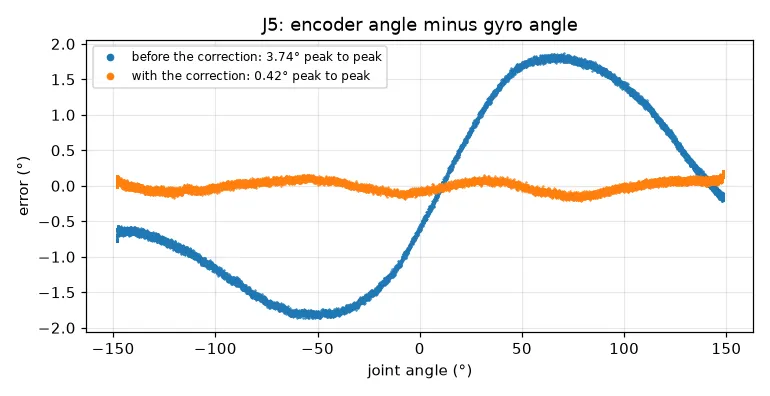
The correction is in mycobot_description/config/mycobot_280_arduino/calibration.yaml:
true angle = encoder angle − e(encoder angle)e(q) = 1.493 sin q + 0.598 sin 2q + 0.018 (cos q − 1) − 0.377 (cos 2q − 1) [degrees]- e(0) = 0, so the zero pose does not change. At 90° the correction is 2.2° (25 servo steps).
position_to_angleandangle_to_positionin the Julia package apply it. Plans, recordings and the IMU fit use corrected angles from commit a1d79a1 on. Recordings made before that have encoder angles.- The firmware and the Control page do not apply it. They serve every user’s arm, so the correction must be stored on each ATOM first (roadmap).
- Check with the gravity data: with J5 corrected, the IMU model of the static poses fits better, 0.84° → 0.48° RMS (worst pose 2.29° → 1.09°).
What this changes
Section titled “What this changes”- The joint zeros do not need a correction.
- J5’s encoder error is corrected in the Julia package (above).
- The play of J2–J4 and the bending of J2 need a gravity model. With the masses, the sign of the gravity torque tells which side of the play the link rests on.
- The servo encoders do not measure the flange position to better than a few millimetres. Measure accuracy with an external reference (pen on paper, a dial gauge, a cone plate) or with the IMU.