

Onboard control and vibration
Onboard loop
Section titled “Onboard loop”| ATOM (controller firmware) | Laptop (Julia) | |
|---|---|---|
| Loop rate | 500.0 Hz | ~285–300 Hz |
| Period | 1.985–2.016 ms, 0 late cycles | stalls of 30–80 ms |
| Telemetry | 7750 of 7750 samples per circle run, over WiFi | — |
| Circle, lag compensation | 5.0 mm RMS | 5.0 mm RMS |
| Circle, ILC iteration 3 | 1.0 mm RMS | 0.8 mm RMS |
The tracking accuracy is the same. In position mode, the servos (lag and sticking) limit the accuracy, not the loop rate. The onboard loop gives deterministic timing and room for feedback control.
End-effector vibration
Section titled “End-effector vibration”The IMU is at the end effector. The vibration is the acceleration and the rotation rate above ~2.5 Hz (the signal minus its 0.2 s moving average), on the circle part of the run:
| Run (ATOM) | Error (RMS) | Acceleration RMS / peak | Rotation rate RMS / peak |
|---|---|---|---|
| Lag compensation | 5.0 mm | 242 mg / 1.79 g | 11.5 / 60°/s |
| ILC 1 | 2.6 mm | 237 mg / 1.58 g | 11.3 / 64°/s |
| ILC 2 | 1.5 mm | 242 mg / 2.03 g | 10.9 / 82°/s |
| ILC 3 | 1.0 mm | 249 mg / 1.52 g | 10.4 / 69°/s |
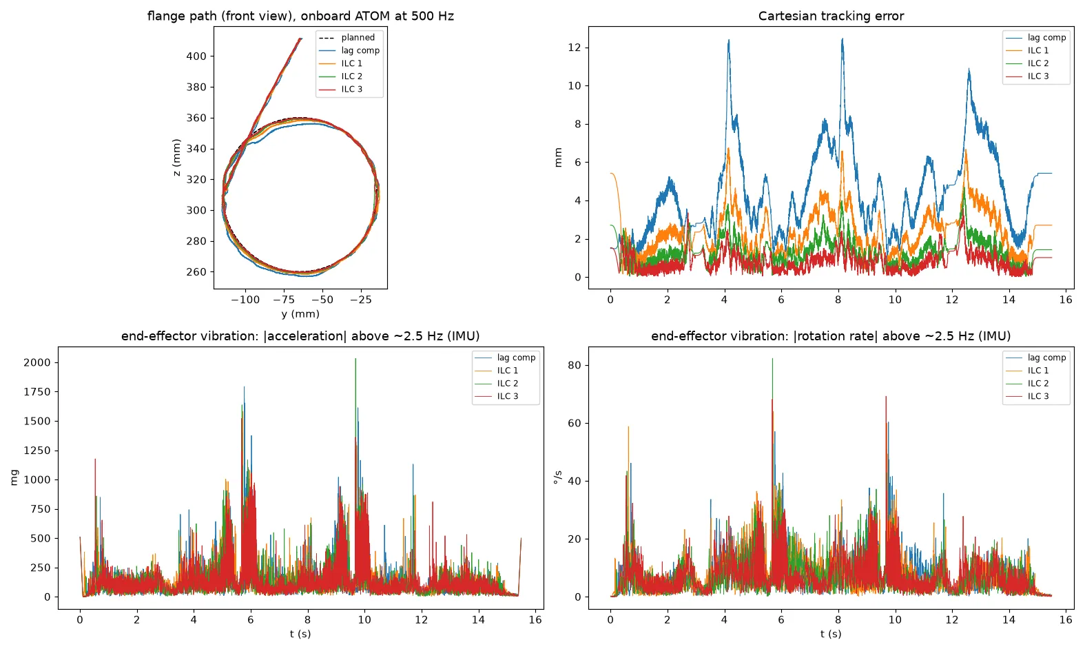
- ILC reduces the position error by 5× but does not change the vibration. ILC learns only slow position errors.
- The vibration comes in bursts at the same point of each lap (≈5.7–6.1 s and 9.6–10.1 s). This is just after J1 and J5 reverse, while J3 and J4 reverse. It is not where the position error peaks.
- Probable causes: gear backlash when the load direction changes, or servo jitter. This is not verified.
Next experiments
Section titled “Next experiments”- Set the servo acceleration register to 50 (the value that the stock firmware uses) instead of 0, and compare the vibration.
- Use the IMU as a cost in planning or learning.